From Bubbles to Bandpass Filters: An Electrical Analogy for Minnaert Resonance in Rain Sounds
A mathematical explanation of RLC circuit modeling of raindrop bubble oscillations, bridging fluid dynamics and electronic filter theory.
Most people know the sound of rain on water, but few stop to think about what actually makes that sound. When a raindrop hits water, it creates a small bubble which then vibrates at a particular frequency. The study of these vibrations dates back to 1933, when Marcel Minnaert first described the phenomenon that bears his name.
What is interesting, and what this essay will show, is that these bubble vibrations can be understood using the same mathematics we use to describe electrical circuits. By treating the bubble as an RLC circuit, we can calculate exactly what sound it will make without having to measure it directly. This approach allows us to synthesize realistic rain sounds on a computer, using only fundamental physical constants rather than guesswork.
How Bubbles Make Sound
Anyone who has watched rain hit water knows about the little sounds each drop makes. What most people do not realize is that each sound comes from a tiny bubble of air that vibrates like a bell. The larger the bubble, the lower the note it produces. Smaller bubbles make higher notes.
This relationship was worked out by Marcel Minnaert in 1933. He showed that the frequency of a bubble depends only on its size - a very simple and elegant result that has proved useful in many fields beyond acoustics.
The practical problem for anyone who wants to create realistic rain sounds on a computer is how to model these bubbles correctly. Most existing methods either use recorded samples (which repeat) or adjust filters by hand (which never quite sounds right). Neither approach is satisfactory for long listening sessions.
The key insight is to recognize that a vibrating bubble is just another form of harmonic oscillator. It has a spring element (the compressed air) and a mass element (the surrounding water). Working from this simple model, we can apply the centuries-old analogy between mechanical and electrical systems. A bubble is to acoustics what an RLC circuit is to electronics - both store and release energy in predictable ways.
The benefit of this approach is that every element of our model has a clear physical meaning. There are no mysterious parameters to adjust because everything comes from fundamental properties of water and air. The mathematics may look intimidating at first, but the ideas behind them are simple and clear.
The Bubble as a Simple Model
To understand how a bubble makes sound, we need to think about it as a simple harmonic oscillator. It has three essential parts:
- The air inside the bubble, which can be compressed and so acts like a spring
- The water surrounding the bubble, which has mass and must be moved
- The ways that energy can be lost, through sound and through friction
When these three parts work together, the bubble vibrates at its natural frequency. This frequency depends mainly on the bubble's size - a fact that Minnaert showed in his original work. The mathematics behind this relationship comes from the balance between the spring force of the compressed air and the inertia of the surrounding water.
What is remarkable about this system is that it can be described completely by the same mathematics electrical engineers use to design simple circuits. This is not a rough analogy or approximation. The correspondence is exact, which means we can borrow all the tools that have been developed over many years for analyzing electrical circuits.
- Spring force: The compression of air inside the bubble
- Inertial force: The mass of water that must be moved during oscillation
- Damping forces: Energy loss through acoustic radiation and viscous friction
Each of these phenomena will map to a specific electrical component, creating a complete circuit model of the bubble oscillator. The beauty of this approach is that well-documented circuit analysis techniques can then be applied to predict the acoustic behavior of bubbles across a wide range of sizes and conditions.
Translating to Circuits
The correspondence between mechanical systems and electrical circuits has been understood for many years. A bubble in water maps to an electrical circuit in the following way:
| What happens in the bubble | What it means in electricity | The component itself |
|---|---|---|
| Force pushes the water | Voltage pushes current | A voltage source |
| Water moves back and forth | Current flows in wire | The current itself |
| Mass of water must be moved | Inductance stores energy in magnetic field | A coil of wire |
| Air compresses like a spring | Capacitance stores energy in electric field | A capacitor |
| Energy is lost as sound and friction | Resistance turns current into heat | A resistor |
This means we can represent a bubble as a simple RLC circuit - a resistance, inductance, and capacitance all in series. The beauty of this approach is that once we have an RLC circuit, we can solve it with methods that have been used in electrical engineering for a century.
For our bubble:
- The inductance comes from mass of water that has to move
- The capacitance comes from how much the air inside can be compressed
- The resistance comes from ways that energy can escape
The frequency at which the bubble naturally vibrates is determined only by the inductance and capacitance, while the resistance determines how long the vibration lasts. This is exactly the same way that a radio circuit works: inductance and capacitance set the station frequency, while resistance determines how sharply the circuit is tuned.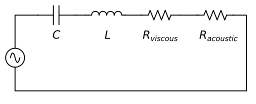
Capacitive Component: Air Compressibility
The capacitive element in our circuit analogy represents the spring-like behavior of compressed air inside the bubble. As the bubble oscillates, the air compresses and expands, storing and releasing energy much like an electrical capacitor stores charge.
Starting with the adiabatic process relation for air:
$$P/P_0 = (V_0/V)^k$$
Where:
- $P$ is the instantaneous pressure
- $P_0$ is the equilibrium pressure (atmospheric pressure: 101,325 Pa)
- $V$ is the instantaneous volume
- $V_0$ is the equilibrium volume
- $k$ is the polytropic index (≈1.4 for air)
Expressing pressure as a function of volume:
$$P = P_0 \left(\frac{V_0}{V}\right)^k$$
Calculating the derivative with respect to volume:
$$\frac{dP}{dV} = \frac{d}{dV}\left[P_0 \left(\frac{V_0}{V}\right)^k\right] = -\frac{k P_0 \left(\frac{V_0}{V}\right)^k}{V}$$
For small oscillations around equilibrium, we can approximate $V \approx V_0$:
$$\frac{dP}{dV} \approx -\frac{k P_0}{V_0}$$
Using the sign convention where compression represents negative volume flow, the mechanical capacitance becomes:
$$C = -\frac{1}{\frac{dP}{dV}} = \frac{V_0}{kP_0}$$
For a spherical bubble, where $V_0 = \frac{4}{3}\pi r_0^3$ in terms of bubble radius $r_0$:
$$C = \frac{4\pi r_0^3}{3kP_0}$$
The physical interpretation is clear: capacitance represents how much volume change occurs for a given pressure change, capturing the spring-like behavior of the compressed air. A larger bubble (greater $V_0$) has higher capacitance (more "springiness"), while higher pressure or polytropic index reduces capacitance (stiffer spring).
Inductive Component: Water Mass Inertia
The inductive element arises from the mass of water that must be accelerated during bubble oscillation. In acoustic systems, inductance represents the mass per unit area that participates in the oscillatory motion.
For oscillating spherical waves, we consider the contribution of thin spherical shells of water at increasing distances from the bubble surface. For a shell at radius $r$ with thickness $dr$:
$$dL = \frac{\rho \cdot dr}{4\pi r^2}$$
Where:
- $\rho$ (rho) is the density of water (1,000 kg/m³)
- $4\pi r^2$ is the surface area of the spherical shell
To account for the total effective mass that must be moved during bubble oscillation, we integrate from the bubble surface $r_0$ to infinity:
$$L = \int_{r_0}^{\infty} \frac{\rho}{4\pi r^2} dr = \frac{\rho}{4\pi} \int_{r_0}^{\infty} \frac{1}{r^2} dr$$
Evaluating the integral:
$$L = \frac{\rho}{4\pi} \left[-\frac{1}{r}\right]_{r_0}^{\infty} = \frac{\rho}{4\pi} \left(0 - \left(-\frac{1}{r_0}\right)\right) = \frac{\rho}{4\pi r_0}$$
Substituting the density of water:
$$L = \frac{\rho_{water}}{4\pi r_0}$$
The physical interpretation is elegant: the inductance represents the effective mass of water that must be accelerated during bubble oscillation. The integration to infinity accounts for the fact that bubble oscillations affect water at all distances, though the influence diminishes with $r^2$. A larger bubble radius results in smaller inductance—intuitively, a larger bubble moves more water but distributes the effect over a larger surface area.
Acoustic Radiation Resistance
Energy dissipation in the oscillating system occurs through two primary mechanisms. The first is acoustic radiation resistance, which represents the energy lost as sound waves propagate away from the oscillating bubble through the surrounding water.
The characteristic impedance of any medium describes its resistance to acoustic wave propagation:
$$Z = \rho c$$
Where:
- $\rho$ is the medium density
- $c$ is the speed of sound in the medium
For water as the surrounding medium, the acoustic radiation resistance becomes:
$$R_{acoustic} = \rho_{water} \cdot c_{water}$$
Where:
- $\rho_{water} = 1,000 \text{ kg/m³}$ (density of water)
- $c_{water} = 1,482 \text{ m/s}$ (speed of sound in water at 20°C)
Thus:
$$R_{acoustic} = 1,000 \times 1,482 = 1.482 \times 10^6 \text{ kg/(m²·s)}$$
The physical interpretation is straightforward: as the bubble oscillates, it radiates sound waves outward through the water. The characteristic impedance of water determines how "difficult" it is for these waves to propagate, which appears as an energy loss (resistance) in the circuit analogy.
A higher characteristic impedance means more energy is radiated away per oscillation cycle, damping the oscillation more quickly. This explains why the radiation resistance becomes a key component in determining the quality factor of the bubble resonance. The contrast with air's characteristic impedance ($\rho_{air} \cdot c_{air} \approx 420$) highlights why bubble sounds are so efficient in water—the impedance mismatch is significant, making water an excellent medium for acoustic energy transfer.
Viscous Resistance
The second energy dissipation mechanism is viscous resistance, which represents energy loss due to fluid friction at the bubble-water interface. Starting from the fundamental definition of viscosity (Newton's law of viscosity):
$$F = \mu \cdot A \cdot \frac{v}{y}$$
Where:
- $F$ is the force opposing motion
- $\mu$ (mu) is the dynamic viscosity of water
- $A$ is the surface area
- $v$ is the relative velocity
- $y$ is the characteristic distance (boundary layer thickness)
Dividing both sides by area to get pressure:
$$P = \mu \cdot \frac{v}{y}$$
Since the volume flow rate $\frac{dV}{dt} = v \cdot A_{surface}$, we have:
$$v = \frac{dV/dt}{A_{surface}}$$
Substituting:
$$P = \mu \cdot \frac{dV/dt}{A_{surface} \cdot y}$$
Assuming the boundary layer thickness $y$ is proportional to the bubble radius $r_0$, and noting that the bubble volume $V_0 \propto A_{surface} \cdot r_0$, we can simplify:
$$P = k \cdot \frac{dV/dt}{V_0}$$
Where $k$ is a proportionality constant that incorporates viscosity and geometric factors. The viscous resistance then becomes:
$$R_{viscous} = \frac{k}{V_0} = \frac{k}{\frac{4}{3}\pi r_0^3}$$
The experimentally determined value of $k \approx 1$ Pa·s represents the effective viscosity including all geometric factors specific to bubble oscillation in water.
The physical interpretation is that viscous resistance represents energy loss due to internal friction in the surrounding water. The key insight is that resistance scales with $1/r_0^3$—smaller bubbles experience relatively more viscous damping because their volume-to-surface-area ratio is less favorable.
Resonant Frequency and Quality Factor
With all three circuit components defined, we can now derive the complete acoustic behavior of our bubble oscillator.
Resonant Frequency
For a series RLC circuit, the natural resonant frequency is:
$$f_0 = \frac{1}{2\pi\sqrt{LC}}$$
Substituting our expressions for $L$ and $C$:
$$f_0 = \frac{1}{2\pi\sqrt{\frac{\rho_{water}}{4\pi r_0} \cdot \frac{4\pi r_0^3}{3kP_0}}}$$
$$f_0 = \frac{1}{2\pi} \sqrt{\frac{3kP_0}{\rho_{water} r_0^2}}$$
This represents the fundamental resonant frequency that emerges from the physical properties of the bubble-water system. The frequency is inversely proportional to the bubble radius and directly proportional to the square root of atmospheric pressure.
Quality Factor
The quality factor, which describes how sustained the oscillations are, follows the standard RLC circuit relationship:
$$Q = \frac{1}{R} \sqrt{\frac{L}{C}}$$
Substituting our component expressions:
$$Q = \frac{1}{R_{acoustic} + R_{viscous}} \cdot \sqrt{\frac{\rho_{water}}{4\pi r_0} \cdot \frac{kP_0}{4\pi r_0^3/3}}$$
$$Q = \frac{1}{R_{acoustic} + R_{viscous}} \cdot \sqrt{\frac{3kP_0\rho_{water}}{(4\pi r_0)^2 r_0^2}}$$
Several insights emerge from this expression:
- Scale dependency: Q scales as $r_0^{-2}$, so smaller bubbles have significantly lower Q factors
- Energy balance: Higher resistance (more energy loss) reduces Q, leading to more rapidly damped oscillations
- Physical interpretability: Different bubble sizes and surface conditions naturally produce different sonic characteristics—from tonal, sustained sounds (high Q) to splashy, brief impacts (low Q)
From Theory to Audio Synthesis
The electrical analogy framework transforms a complex problem in computational acoustics into a well-understood circuit design challenge. Each bubble oscillation corresponds to a bandpass filter with physical parameters directly derived from the RLC model:
- Center frequency: Determined by the resonant frequency $f_0$
- Bandwidth: Set by the quality factor Q
- Impulse response: Corresponds to a single drop impact
For digital implementation, the continuous-time RLC circuit is converted to a discrete-time biquad filter using standard techniques such as the bilinear transform. The resulting digital filter processes impulses to generate physically accurate bubble sounds.
In practical implementation, a rain synthesis system proceeds as follows:
- Drop generation: Create raindrops with sizes following the Marshall-Palmer distribution
- Physical parameter calculation: For each drop radius, compute the RLC component values
- Resonance determination: Calculate the corresponding resonant frequency and quality factor
- Filter design: Design bandpass filters with these physical parameters
- Impulse synthesis: Generate impulses filtered through each designed filter
- Spatial processing: Apply propagation effects and binaural panning
The key advantage of this physical approach is that all synthetic sounds automatically inherit realistic frequency content and temporal behavior, without the need for heuristic tuning or arbitrary parameter adjustment. The spectral characteristics, decay rates, and spatial properties all emerge naturally from fundamental physical constants.
References
- Minnaert, M. (1933). "On musical air-bubbles and the sound of running water." Philosophical Magazine, 16(104), 235-248.
- Leighton, T. G. (1994). "The Acoustic Bubble." Academic Press.
- Olson, H. F. (1943). "Dynamical Analogies." D. Van Nostrand Company